As in previous installions we will proceed with a double circuit:
#1. HARDWARE PROVISION:24VDC security voltage present or not present
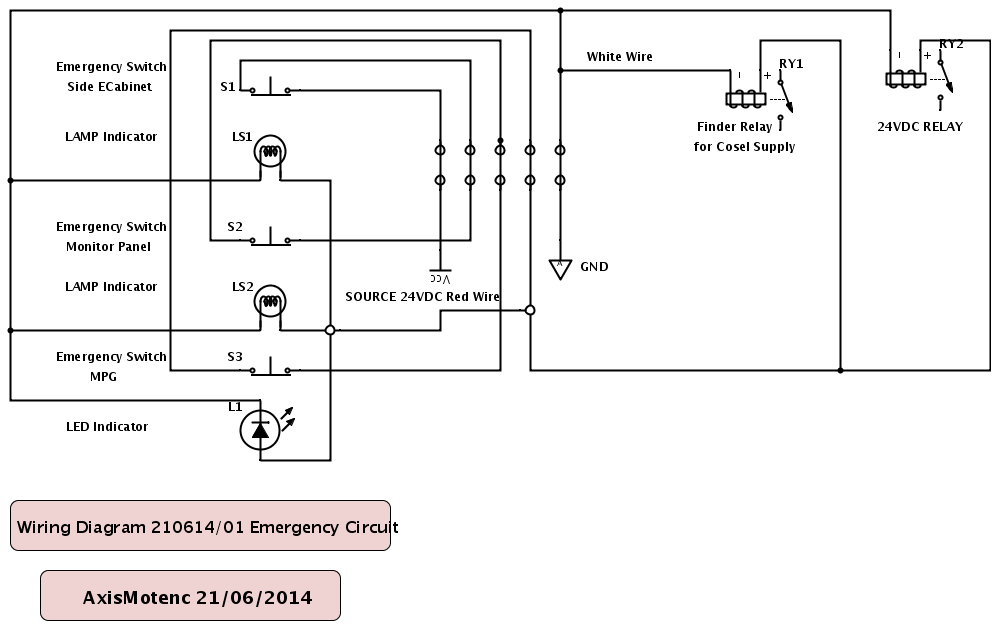
There are tree Mushroom Emergency Switches:
-on the Monitor Panel.
-on the back of the Electrical Cabinet.
-on the Teach Pendant or MPG.
The tree Mushroom Emergency Switches are Normally Closed.
There is a serial connection between these Switches from the 24VDC Power Supply towards
the Binder Relay and Relay01 on the Output Board.
The Binder Relay switches off the Power to the Cosel Power Supply in case of an event.
The Relay01 interrupts 24VDC towards the real world switches & joysticks on the Monitor Panel.
Besides each Emergency Switch there is a 24VDC Lamp (or on the MPG a led) indicator.
This Lamp indicator tells the User if the machine can switch 24VDC or not.
Naming of the Cables:
Sideway of the ECabinet:2306 & 2307
Teach Pendant:2308 & 2309 (black Cables 7 & 8 coming from the Harting Connector)
Monitor Panel:2310 & 2311
#2. SOFTWARE PROVISION:
represented by LinuxCNC software